4 Steps To a Professional Database Design
It includes four steps :
1. Requirement Analysis
The database requirements are determined. The exact requirement of the user from the system is captured.All the relevant information related to the system is gathered. The six most common techniques are:
- Sampling of existing documentation, forms, databases
- Research and site visits
- Observation of the work environment
- Questionnaires
- Prototyping -build a small model of the user’s requirement to verify before hand
- Joint Requirements Planning (JRP)- group meetings are conducted to analyze existing problems
2. Entity Relationship Diagram (ERD)
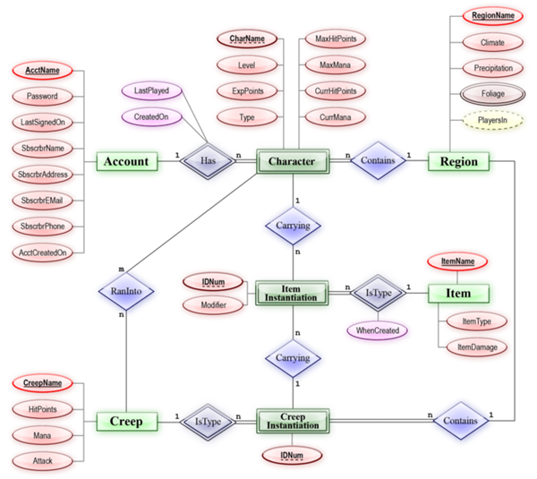
ERD is a high level notation for expressing database designs. It graphically defines the structure of the database in a very simple and understandable manner through the use of symbols.
The information gathered during the ‘Requirement Analysis’ step is transformed into an ERD(Entity Relationship Diagram) that is the data is organized into entities and relationships between them. So instead of going through a lengthy piece of material, we have a pictorial representation of the same piece of information which is easier to read.
A sample ER Diagram is this:

Various data modeling languages can be used to create an ERD like crow’s foot notation, Chen notation, IDEFIX (Integration Definition For Information Modeling), Shading notation, Bachman notation, UML (Unified Modeling Language) standard etc. Wikipedia has a good page about ER diagrams here
3. Relational Model
It is very easy to understand the scenario from an ERD, but the latter is very weak from the implementation point of view. Concepts of subclasses (IS -A structures) and relationships, for example, cannot be implemented in the database directly .At this point relational model comes into play.
A relational model employs a single concept of tables (also called relations).The entity sets and the relationships depicted in the ERD are converted into tables –a relational model.
There are five steps for the conversion:
- Turn each non-weak entity set into its corresponding table with the same set of attributes
- Replace a relationship by a relation whose attributes are the keys of the connecting entity sets
- Some relations can do well if combined or excluded. For example the supporting relationships (for weak entity sets) need not to be converted to relation at all.
- Replace a weak entity set by a relation whose attributes are its own attributes (if any) plus the borrowed attributes that help to make its primary key.
- Convert the subclass structures using the object oriented approach, E/R style conversion or null values.
Explanation of converting ER diagram to relationship model has vast concepts that will not be covered in this post. There are many good books and online resources available that makes it easy to understand. For an overview consider this example that I have taken from Wikipedia:
An idealized, very simple example of a description of some relvars and their attributes:
- Customer(Customer ID, Tax ID, Name, Address, City, State, Zip, Phone)
- Order(Order No, Customer ID, Invoice No, Date Placed, Date Promised, Terms, Status)
- Order Line(Order No, Order Line No, Product Code, Qty)
- Invoice(Invoice No, Customer ID, Order No, Date, Status)
- Invoice Line(Invoice No, Invoice Line No, Product Code, Qty Shipped)
- Product(Product Code, Product Description)
In this design we have six relvars: Customer, Order, Order Line, Invoice, Invoice Line and Product. The bold, underlined attributes are candidate keys. The non-bold, underlined attributes are foreign keys.
4. Normalization
Normalization is a process of increasing the normal form rating .It primarily eliminates the following dependencies in order to avoid redundancies and data anomalies:
- Partial dependency : based on part of the primary key
- Transitive dependence : based on an attribute that is not part of the primary key
The first three forms of normalization are:
- 1NF
- Lowest implementable normal form
- Primary key entity integrity requirements are met
- Each cell contains a single value
- Non-Primary key values are dependent on the primary key
- 2NF
- All 1NF conditions are met
- Partial dependencies are removed
- 3NF
- All 2Nf conditions are met
- Transitive dependencies removed
Higher forms up to 5NF and BCNF (Boyce-Codd Normal Form) also exist.
Normalization can be applied in two ways:
- Normal forms applied after the relational model is created
- The third step is skipped and the creation of tables is done with the normalization in consideration directly


